Ramping with a Timer

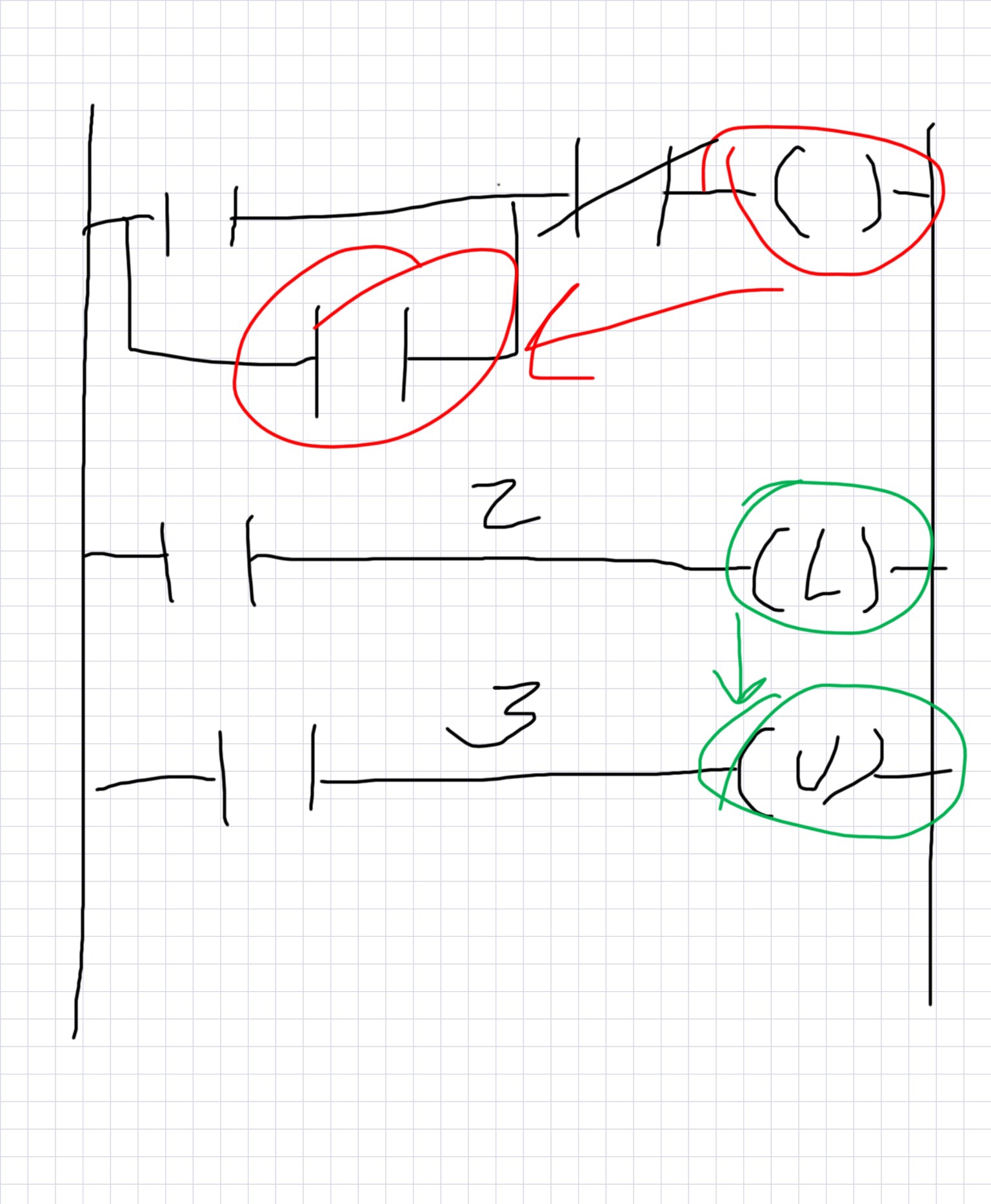
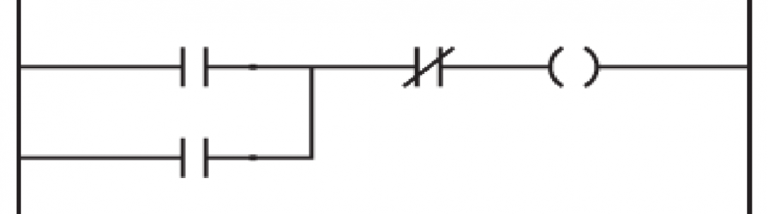
The problem: You have a process that reacts badly when it is energized too quickly (almost every process I touch). This is not a big issue if you have some way to slowly ramp your energy/feed source from a valve, VFD, temp regulator etc…that and a PLC attached to your process with analog output ability. First thing to detmermine on the programming end is how your PLC outputs its signal to your process. For example: is your output 4-20 mA, 0-10V…etc. and how exactly is that translated in your program. When you send a command to the output does it need to be a number from 0-32767, 0-100 percent, or a number related to your process. Second, determine how long you want to ramp and convert it to your PLCs default timer time. ControlLogix does time in milliseconds. So if you want a 10 second ramp you would have to convert it to 10000ms. Now what needs to be done is find out how your time relates to your output. We will go for an easy example of 0-32676 bits out to 10 seconds. So 0 = no output and 32676 = 100 percent output (if you want to ramp to 100%). We will opt for going from 0 to 100% in 10 seconds. If we want this divide 32676 by 10000ms and we get 3.2676 bits per ms. Now, determine what you want to start your ramp (start button, limit switch, proximity switch output, etc…). Latch the bit, as seen in the last blog post. (Simple Latching in a PLC) Now fire a timer (TON) with your latch bit. We want to set the timer to the amout of time you want to ramp, 10000ms is our example. We use the accumulation integer to determine where the timer is in the process and to ramp up the process (yourtimer.ACC in Logix). Now on a branch under the timer convert to your PLCs output using a MUL(multiply) so you will be multiplying your .ACC integer to your factor of 3.2676. This number is what you want to put into your output card with a MOV(Move) instruction. Do this with a bit that comes on while you desire ramping. This can also be a ramp bit or alternatively it can be the timer timing bit (.TT). This will send your output only while your timer timing is high. There are many ways to set and reset your timer/s from here. You may also want to use a recantation timer (RTO) and just user the .ACC to selectively ramp at certain times. If you do this you would also need to reset the timer with a (res) bit. I will post some screenshots or drawings for this soon but for now…I hope this helps you when programming ramps.

Luke

==

Simple Latching in a PLC

Latching can be done in many ways in a PLC. I am sharing a few easy examples to get you started so you will have an idea of what it is when its presented to you. The most simple way to think about a latch is when thinking of an electric motor being turned on with a momentary push button. A momentary push button is not like a light switch that holds its state (the light stays on because the light switch closes the electric circuit and keeps current running through the light bulb). The momentary push button only flashes on for a short amount of time and something else has to maintain the closed circuit. I will talk about 3 simple ways to do this. Method 1 and 2 will be from the the 1st rung in my drawing. Method 3 will be from the second and third rungs on the drawing.

Method 1 – The top rung has a branch with a contact -||- on top which is representative of a push button input into the PLC or any other quick off/on indication. The curly thing on the right hand side is a coil -( )- (output bit). For the first example we will use a reference to the output bit and put it on the branch under the momentary bit. So what this does is if the bit is turned on it also hold the bit high. Further down the rung before the coil is a -|/|- bit (normally closed contact). This bit is high until another button is pushed or some other logic goes high.

Method 2 – Very similar to the one above. The only difference would be on the branch below another contact related to the actual device the PLC is turning on is sending back indication that it was turn on or running. This would be like if you turned on a motor and a contact on the motor sent you a signal that is was running. This type of contact sending running indication is called the Auxiliary contact or AUX for short. This contact would hold the coil/output high until the normally closed contact is pushed (breaking the logic).

Method 3 – Most PLC programs also have a bit called a Latching bit. This bit looks like an L in parenthesis -(L)- . The Latch bit always works with an unlatching bit. The unlatching bit looks like a U in parenthesis -(U)-. This works fairly simple. When you turn on the bit, in this sample I’m just using a simple contact, the latching bit holds high. The bit holds high until the Unlatch bit is made high. In my example I just have another contact which could be representative of a stop or off button.

These samples are really simple and can be made complicated for whatever latching you need for your project. Hope this helps.

Luke

The data collector for a PLC 5 or SLC and how to connect them to modern equipment

Ever try to connect FactoryTalk Linx to an old Rockwell PLC through Ethernet. I still have several in my plant and we were trying to implement a historian with a data collector. I thought it would be a simple conversion through a serial to Ethernet converter from the DF1 port, no…not so easy. Our setup was the new FT Linx on a Windows 10 workstation connected to all the plant PLCs on the same subnet. All the 1756 PLCs and CompactLogix PLCs connected without issue (after naming and setup which I think will be another post). So to start this….if you have old Allen Bradley stuff and haven’t purchased a communications software just pause before you purchase FT Linx. I was told it would work on all our Allen Bradley PLCs but after hours of Allen Bradley tech assistance we could not consistently pull any data from the tags in our equipment. We were told the 1761 Net-ENI would allow communications to the PLC – 5s with FT View but were not successful. The way we ended up connecting to the legacy hardware was with RSLogix Classic OPC server which we added to the FT Linx box (which is not supposed to work according to AB). We also had to use a 1756-DHRIO card in one of our ControlLogix PLCs and connect it to the DH+ line running through one of the cabinets (serious undertaking if the old PLCs are a long ways out). When we installed the card you could see the Control Logic network card in RS Linx, just hit the plus by the card just the same as if you where looking for the Controller under that card. The navigation tree reveals all the contents of the back pane the network card is installed in. Find the DH+ card in the tree then expand it by clicking the plus. Now you should see channel A and channel B. If you put the DH+ line in the right place, numbered it correctly, and have your resistance set up right (whew…) you should see your ancient PLCs under the channel you connected them to. From here…Right click them and Select Create Topic. This will take you to the Topic Configuration screen. Name your PLC something you will remember and click the Apply button. Accept your changes then click Done. Hopefully this helps someone out there…if you have any questions submit a comment and I will answer the best to my knowledge. Thank you for reading, Luke.

Here I go again

Thank you for visiting my page!!

So, now your an engineer….or maybe you’ve been one for a while. I cant remember if its been a while or if I just started sometimes. Electrical engineering was something I sort of fell into after getting bored with a 10 year residential construction career. I blogged back then and liked it but was unable to continue the blog working full time and going to engineering school full time. So here I am again on the other side trying out the blogging life on another subject and in a whole different career. I now have been doing this 10 years ish and realize I could help someone else in this area. If there was a theme to this new blog it would be the same as the last. Kind of a how-to do something only a little different than last time. Hopefully I will be able to help a few of you our there and also hopefully I will learn some new things myself. This business is constantly changing technology and there are new challenges out there just waiting for some engineer to take on. I feel at times I work in a plant full of original machines, or what I like to call it a “Unicorn zoo”. I wished for the first 2 years at my plant someone was there to help or some webpage had something on these old homemade machines. One million square feet of old homemade machines to be specific. I will post on this site as often as I can some instance of trouble I had or on some engineering tricks I’ve learned…..or some other nerd gibberish in the hope that either you like to read my ridiculousness or that I could help you figure something out on that next engineering marvel.

-Luke

post